2016年11月30日星期三

CO-A4 Carbon Monoxide Sensor 4-Electrode

CO-A4 Carbon Monoxide Sensor 4-Electrode

Temperature range :-30 to 50 ℃
Pressure range : 80 to 120 kPa
Humidity range :15 to 90 % rh continuous
Storage period : 6 months @ 3 to 20 ℃ (stored in sealed pot)
Load resistor :33 to 100 Ω (AFE circuit is recommended)
Weight : < 6g
CO-A4 Carbon Monoxide Sensor 4-Electrode

Product Specification

CO-A4 Carbon Monoxide Sensor 4-Electrode

PERFORMANCE
Sensitivity              nA/ppm in 2ppm CO                                           220 to 375
Response time       t90 (s) from zero to 10ppm CO                                     < 20
Zero current          nA in zero air at 20℃                                         -100 to +10
Noise*                  ±2 standard deviations (ppb equivalent)                           20
Range                   ppm limit of performance warranty 500
Linearity                ppm CO error at full scale, linear at zero, 15ppm CO    < ± 1
Overgas limit         maximum ppm for stable response to gas pulse 2000
* Tested with Alphasense AFE low noise circuit

LIFETIME
Zero drift             ppb equivalent change/year in lab air                        < ±100
Sensitivity drift     % change/year in lab air, monthly test                          < 10
Operating life      months until 50% original signal (24 month warranted)   > 36

ENVIRONMENTAL
Sensitivity @ -20℃ (% output @ -20℃/output @ 20℃) @ 5ppm CO        50 to 85
Sensitivity @ 50℃  (% output @ 50℃/output @ 20℃) @ 5ppm CO       110 to 125
Zero @ -20℃        nA change from 20℃                                                10 to 40
Zero @ 50℃         nA change from 20℃                                           -120 to -200

CROSS SENSITIVITY
Filter capacity       ppm·hrs H2S                                               250,000
H2S sensitivity      % measured gas @ 5ppm H2S                         < 0.1
NO2 sensitivity     % measured gas @ 5ppm NO2                          < -2
Cl2 sensitivity       % measured gas @ 5ppm Cl2                          < 0.1
NO sensitivity       % measured gas @ 5ppm NO                           < -2
SO2 sensitivity      % measured gas @ 5ppm SO2                        < 0.1
H2 sensitivity        % measured gas @ 100ppm H2  at 20℃           < 10
C2H4 sensitivity    % measured gas @ 100ppm C2H4                   < 0.5
NH3 sensitivity     % measured gas @ 20ppm NH3                       < 0.1
KEY SPECIFICATIONS
Temperature range   ℃                                                             -30 to 50
Pressure range          kPa                                                          80 to 120
Humidity range         % rh continuous                                          15 to 90
Storage period          months @ 3 to 20 ℃ (stored in sealed pot)              6
Load resistor            Ω (AFE circuit is recommended)                  33 to 100
Weight                    g                                                                      < 6

2016年11月29日星期二

SFO-W Spot-Welded Strain Sensor Fiber Optic Strain Sensor

SFO-W Spot-Welded Strain Sensor Fiber Optic Strain Sensor - SFO-W

Immune to EMI/RFI/lightning
Intrinsically safe
Static/dynamic response
High sensitivity and resolution: 0.01% full scale
Signal transmitted over long distances
No interference due to fiber bending
Absolute measurements in engineering units
Data-acquisition compatible
SFO-W Spot-Welded Strain Sensor Fiber Optic Strain Sensor

Product Specification

SFO-W Spot-Welded Strain Sensor Fiber Optic Strain Sensor
The SFO-W is a fi ber optic, spot-welded strain sensor designed for civil engineering applications such as the monitoring of dams, bridges, tunnels, and other structures.
The SFO-W strain sensor offers small size, high accuracy, immunity to EMI/RFI, and resistance to corrosive environments with a high temperature range.
Key Features
Immune to EMI/RFI/lightning
Intrinsically safe
Static/dynamic response
High sensitivity and resolution: 0.01% full scale
Signal transmitted over long distances
No interference due to fiber bending
Absolute measurements in engineering units
Data-acquisition compatible
Applications
Steel structures
Dams
Nuclear power plants
Structural members of buildings and bridges
Tunnel supports
Corrosive environments
High EMI/RFI environments
Specifications
Strain range : ±1000 µε , ±1500 µε , ±2000 µε
Resolution : 0.01% of full scale
Transverse sensitivity : < 0.1% of full scale
Connector type : ST connector
Operating temperature : -55℃ to 85℃ (-67℉ to 185℉)


2016年11月24日星期四

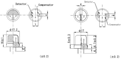
NEMOTO flammable gas sensors - NAP-100AM

NEMOTO flammable gas sensors - NAP-100AM

NAP-100 series are flammable gas sensors for industrial applications, and 4 types are provided for users’ choice. For detailed technical information, please refer to the individual user’s manuals.
NEMOTO  flammable gas sensors

Product Specification

NAP-100 series are flammable gas sensors for industrial applications, and 4 types are provided for users’ choice. For detailed technical information, please refer to the individual user’s manuals.
* Ratings and gas sensitivity
Items
NAP-100AM NAP-100AC NAP-100AD NAP-100AH
Supply voltage
2.6V 2.6V 2.6V 1.6V
Current
160 ~ 180mA 160 ~ 180mA 160 ~ 180mA 120 ~ 140mA
Ambient temp. &
-10 ~ +50℃ -10 ~ +50℃ 260℃ or less 260℃ or less
humidity in operation
95%RH or less 95%RH or less 95%RH or less 95%RH or less
Ambient temp. &
-20 ~ +60℃ -20 ~ +60℃ -20 ~ +60℃ -20 ~ +60℃
humidity in storage
99%RH or less 99%RH or less 99%RH or less 99%RH or less
Applications
Universal type For higher conc. For high temp. For H2 only
Target gases
Flammable Flammable Flammable H2、CO
Detection range in high
1 ~ 50%LEL 3 ~ 100%LEL 1 ~ 50%LEL 1 ~ 50%LEL
accuracy


2016年11月23日星期三

FOT-M Temperature Sensor Fiber Optic Temperature Sensor

FOT-M Temperature Sensor Fiber Optic Temperature Sensor

Intrinsically safe
Immune to EMI/RFI
Up to 85℃ (180℉)
Accuracy of ±0.3℃
Miniature and rugged sensor
Fast response time
FOT-M Temperature Sensor Fiber Optic Temperature Sensor

Product Specification

FOT-M Temperature Sensor
The FOT-M is a fiber optic temperature sensor specifi cally designed for med-ical applications. The FOT-M temperature sensor combines all the desired characteristics you would expect from the ideal sensor. Its compact size, immunity to microwave and RF, resistance to corrosion, high accuracy and reliability make it the best choice for temperature measurements in harsh environments.
FISO’s FOT-M fiber optic temperature sensor features complete immunity to EMI and RFI, built-in safety for medical applications, and high accuracy for temperature measurement. The FOT-M temperature sensor provides the medical industry with higher fi delity temperature measurements for demanding applications, like MRI applications.
Key Features
Intrinsically safe
Immune to EMI/RFI
Up to 85℃ (180℉)
Accuracy of ±0.3℃
Miniature and rugged sensor
Fast response time  
Applications
Medical applications
Industrial environments
Harsh and hazardous environments
MRI environment
Immune to microwaves and RF  
Specifi cations
Temperature range:20℃ to 85℃ (68℉ to 185℉)
Resolution (*1) : 0.1℃
Accuracy: ±0.3℃
Response time: Less than 750 ms
Connector type: ST connector
*1. Signal conditioner dependent

2016年11月20日星期日

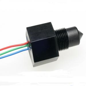
Standard and Extended Temperature Optical Liquid Level Sensors - LLC200D324-003

Standard and Extended Temperature Optical Liquid Level Sensors - LLC200D324-003

Standard and Extended Temperature Industrial Series Optical Liquid Level Sensors
  • Standard and Extended Temperature Optical Liquid Level Sensors

Product Specification

GENERAL DESCRIPTION
The LLC Industrial Series liquid level sensor provides single point liquid detection via a TTL compatible output.
This  sensor  range  was  designed  to  directly  switch incandescent indicators, sounders, relays or applications which require higher output power.

An infra-red LED and phototransistor accurately positioned at the base of the sensing tip ensure good optical coupling between the two when the sensor is in air. When the sensing tip is immersed in liquid, the infra-red light escapes from the cone causing a change in the amount of light detected at the phototransistor which makes the output change state. Various electrical outputs are available to suit different applications.

CLEANING
Proper fluids should be selected based on type of contamination to be removed. SST Sensing recommends freon and alcohol based solvents. DO NOT use chlorinated
solvents such as tricholorethane as these are likely to attack the sensor material.
LIQUID MEDIA COMPATIBILITY
Before use check that the fluid in which you wish to use these devices is compatible with either polysulphone or trogamid.

2016年11月18日星期五

NTM SenseH2 Hydrogen Sensor - SenseH2

NTM SenseH2 Hydrogen Sensor - SenseH2

High sensitivity and selectivity to hydrogen
Fast response and recovery times
Immune to signal saturation
Robust to widely varying ambient flow rates
Compact and rugged design
1.0 to 4.5V output, spans 0.25 to 4.0% H2 in air(5 to 100% LFL)
UL Classified, ATEX, CE for hazardous locations
NTM SenseH2 Hydrogen Sensor

Product Specification

Overview

Designed for hydrogen monitoring, this ceramic sensor exhibits a highly sensitive, selective, and rapid response to the
presence of hydrogen in ambient air. It reliably measures H2 concentrations over a wide range of temperature and
humidity variation and provides a repeatable response, even in the presence of other combustible gases. Additionally,
the NTM SenseH2® hydrogen sensor is immune to signal saturation upon continuous exposure to low levels of hydrogen,
and recovers rapidly and completely upon hydrogen removal.

System Components

Sensor: The sensor element employs a patent‐pending, chemi‐resistive ceramic technology, which provides accurate
and reliable hydrogen detection.


Features

High sensitivity and selectivity to hydrogen
Fast response and recovery times
Immune to signal saturation
Robust to widely varying ambient flow rates
Compact and rugged design
1.0 to 4.5V output, spans 0.25 to 4.0% H2 in air(5 to 100% LFL)
UL Classified, ATEX, CE for hazardous locations

Table of Typical Characteristics

Metric Min Max Units
Characteristics:
H2 range (in air) 0.25 4 %
Voltage input 12 24 Vdc
Output (sensing range) 1 4.5 Vdc
Error state (output signal) 0.5 0.5 Vdc
Error state (output signal) 4.75 4.75 Vdc
Power consumption (25°C) 0.1 0.15 A
Response time (T90) 5 Sec.
Recovery time (T10) 5 Sec.
Environmental Conditions:
Ambient temperature ‐20 80 °C
Relative humidity 5 95 %R.H.
Linear flow rate 0.02 5 m/s

2016年11月17日星期四

What is Electrochemical gas sensor?

What is Electrochemical gas sensor?

4-Electrode Nitric Oxide Sensor
Electrochemical gas sensors are gas detectors that measure the concentration of a target gas by oxidizing or reducing the target gas at an electrode and measuring the resulting current.
Gas detector
A gas detector is a device that detects the presence of gases in an area, often as part of a safety system. This type of equipment is used to detect a gas leak or other emissions and can interface with a control system so a process can be automatically shut down. A gas detector can sound an alarm to operators in the area where the leak is occurring, giving them the opportunity to leave. This type of device is important because there are many gases that can be harmful to organic life, such as humans or animals.
Gas detectors can be used to detect combustible, flammable and toxic gases, and oxygen depletion. This type of device is used widely in industry and can be found in locations, such as on oil rigs, to monitor manufacture processes and emerging technologies such as photovoltaic. They may be used in firefighting.
Gas leak detection is the process of identifying potentially hazardous gas leaks by sensors. These sensors usually employ an audible alarm to alert people when a dangerous gas has been detected. Exposure to toxic gases can also occur in operations such as painting, fumigation, fuel filling, construction, excavation of contaminated soils, landfill operations, entering confined spaces, etc. Common sensors include combustible gas sensors, photoionization detectors, infrared point sensors, ultrasonic sensors, electrochemical gas sensors, and semiconductor sensors. More recently, infrared imaging sensors have come into use. All of these sensors are used for a wide range of applications and can be found in industrial plants, refineries, pharmaceutical manufacturing, fumigation facilities, paper pulp mills, aircraft ans ship-building facilities, hazmat operations, waste-water treatment facilities, vehicles, indoor air quality testing and homes.
Electrochemical gas sensor
SO2-B4 Sulfur Dioxide Sensor 4-Electrode
Electrochemical gas detectors work by allowing gases to diffuse through a porous membrane to an electrode where it is either chemically oxidized or reduced. The amount of current produced is determined by how much of the gas is oxidized at the electrode, indicating the concentration of the gas. Manufactures can customize electrochemical gas detectors by changing the porous barrier to allow for the detection of a certain gas concentration range. Also, since the diffusion barrier is a physical/mechanical barrier, the detector tended to be more stable and reliable over the sensor's duration and thus required less maintenance than other early detector technologies.
However, the sensors are subject to corrosive elements or chemical contamination and may last only 1–2 years before a replacement is required. Electrochemical gas detectors are used in a wide variety of environments such as refineries, gas turbines, chemical plants, underground gas storage facilities, and more.
Construction
The sensors contain two or three electrodes, occasionally four, in contact with an electrolyte. The electrodes are typically fabricated by fixing a high surface area precious metal on to the porous hydrophobic membrane. The working electrode contacts both the electrolyte and the ambient air to be monitored usually via a porous membrane. The electrolyte most commonly used is a mineral acid, but organic electrolytes are also used for some sensors. The electrodes and housing are usually in a plastic housing which contains a gas entry hole for the gas and electrical contacts.
Diffusion controlled response
The magnitude of the current is controlled by how much of the target gas is oxidized at the working electrode. Sensors are usually designed so that the gas supply is limited by diffusion and thus the output from the sensor is linearly proportional to the gas concentration. This linear output is one of the advantages of electrochemical sensors over other sensor technologies, (e.g. infrared), whose output must be linearized before they can be used. A linear output allows for more precise measurement of low concentrations and much simpler calibration (only baseline and one point are needed).
Diffusion control offers another advantage. Changing the diffusion barrier allows the sensor manufacturer to tailor the sensor to a particular target gas concentration range. In addition, since the diffusion barrier is primarily mechanical, the calibration of electrochemical sensors tends to be more stable over time and so electrochemical sensor based instruments require much less maintenance than some other detection technologies. In principle, the sensitivity can be calculated based on the diffusion properties of the gas path into the sensor, though experimental errors in the measurement of the diffusion properties make the calculation less accurate than calibrating with test gas.
Cross sensitivity
For some gases such as ethylene oxide, cross sensitivity can be a problem because ethylene oxide requires a very active working electrode catalyst and high operating potential for its oxidation. Therefore gases which are more easily oxidized such as alcohols and carbon monoxide will also give a response. Cross sensitivity problems can be eliminated though through the use of a chemical filter, for example filters that allows the target gas to pass through unimpeded, but which reacts with and removes common interferences.
While electrochemical sensors offer many advantages, they are not suitable for every gas. Since the detection mechanism involves the oxidation or reduction of the gas, electrochemical sensors are usually only suitable for gases which are electrochemically active, though it is possible to detect electrochemically inert gases indirectly if the gas interacts with another species in the sensor that then produces a response. Sensors for carbon dioxide are an example of this approach and they have been commercially available for several years.

2016年11月15日星期二

What is a Fiber optic sensor?

What is a Fiber optic sensor?
A fiber optic sensor is a sensor that uses optical fiber either as the sensing element ("intrinsic sensors"), or as a means of relaying signals from a remote sensor to the electronics that process the signals ("extrinsic sensors"). Fibers have many uses in remote sensing. Depending on the application, fiber may be used because of its small size, or because no electrical power is needed at the remote location, or because many sensors can be multiplexed along the length of a fiber by using light wavelength shift for each sensor, or by sensing the time delay as light passes along the fiber through each sensor. Time delay can be determined using a device such as an optical time-domain reflectometer and wavelength shift can be calculated using an instrument implementing optical frequency domain reflectometry.
Fiber optic sensors are also immune to electromagnetic interference, and do not conduct electricity so they can be used in places where there is high voltage electricity or flammable material such as jet fuel. Fiber optic sensors can be designed to withstand high temperatures as well.

Intrinsic sensors

Optical fibers can be used as sensors to measure strain,temperature sensor, pressure sensor and other quantities by modifying a fiber so that the quantity to be measured modulates the intensity, phase, polarization, wavelength or transit time of light in the fiber. Sensors that vary the intensity of light are the simplest, since only a simple source and detector are required. A particularly useful feature of intrinsic fiber optic sensors is that they can, if required, provide distributed sensing over very large distances.
Temperature can be measured by using a fiber that has evanescent loss that varies with temperature, or by analyzing the Rayleigh Scattering, Raman scattering or the Brillouin Scattering in the optical fiber. Electrical voltage can be sensed by nonlinear optical effects in specially-doped fiber, which alter the polarization of light as a function of voltage or electric field. Angle measurement sensors can be based on the Sagnac effect.
Special fibers like long-period fiber grating (LPG) optical fibers can be used for direction recognition. Photonics Research Group of Aston University in UK has some publications on vectorial bend sensor applications.
Optical fibers are used as hydrophones for seismic and sonar applications. Hydrophone systems with more than one hundred sensors per fiber cable have been developed. Hydrophone sensor systems are used by the oil industry as well as a few countries' navies. Both bottom-mounted hydrophone arrays and towed streamer systems are in use. The German company Sennheiser developed a laser microphone for use with optical fibers.
A fiber optic microphone and fiber-optic based headphone are useful in areas with strong electrical or magnetic fields, such as communication amongst the team of people working on a patient inside a magnetic resonance imaging (MRI) machine during MRI-guided surgery.
Optical fiber sensors for temperature and pressure have been developed for downhole measurement in oil wells.The fiber optic sensor is well suited for this environment as it functions at temperatures too high for semiconductor sensors (distributed temperature sensing).
Optical fibers can be made into interferometric sensors such as fiber optic gyroscopes, which are used in the Boeing 767 and in some car models (for navigation purposes). They are also used to make hydrogen sensors.
Fiber-optic sensors have been developed to measure co-located temperature and strain simultaneously with very high accuracy using fiber Bragg gratings.This is particularly useful when acquiring information from small or complex structures.Fiber Bragg grating sensors are also particularly well suited for remote monitoring, and they can be interrogated 250 km away from the monitoring station using an optical fiber cable.Brillouin scattering effects can also be used to detect strain and temperature over large distances (20–120 kilometers).

Other examples

A fiber-optic AC/DC voltage sensor in the middle and high voltage range (100–2000 V) can be created by inducing measurable amounts of Kerr nonlinearity in single mode optical fiber by exposing a calculated length of fiber to the external electric field.The measurement technique is based on polarimetric detection and high accuracy is achieved in a hostile industrial environment.
High frequency (5 MHz–1 GHz) electromagnetic fields can be detected by induced nonlinear effects in fiber with a suitable structure. The fiber used is designed such that the Faraday and Kerr effects cause considerable phase change in the presence of the external field. With appropriate sensor design, this type of fiber can be used to measure different electrical and magnetic quantities and different internal parameters of fiber material.
Electrical power can be measured in a fiber by using a structured bulk fiber ampere sensor coupled with proper signal processing in a polarimetric detection scheme. Experiments have been carried out in support of the technique.
Fiber-optic sensors are used in electrical switchgear to transmit light from an electrical arc flash to a digital protective relay to enable fast tripping of a breaker to reduce the energy in the arc blast.
Fiber Bragg grating based fiber optic sensors significantly enhance performance, efficiency and safety in several industries. With FBG integrated technology, sensors can provide detailed analysis and comprehensive reports on insights with very high resolution. These type of sensors are used extensively in several industries like telecommunication, automotive, aerospace, energy, etc.[citation needed] Fiber Bragg gratings are sensitive to the static pressure, mechanical tension and compression and fiber temperature changes. The efficiency of fiber Bragg grating based fiber optic sensors can be provided by means of central wavelength adjustment of light emitting source in accordance with the current Bragg gratings reflection spectra.

Extrinsic sensors

Extrinsic fiber optic sensors use an optical fiber cable, normally a multimode one, to transmit modulated light from either a non-fiber optical sensor, or an electronic sensor connected to an optical transmitter. A major benefit of extrinsic sensors is their ability to reach places which are otherwise inaccessible. An example is the measurement of temperature inside aircraft jet engines by using a fiber to transmit radiation into a radiation pyrometer located outside the engine. Extrinsic sensors can also be used in the same way to measure the internal temperature of electrical transformers, where the extreme electromagnetic fields present make other measurement techniques impossible.
Extrinsic fiber optic sensors provide excellent protection of measurement signals against noise corruption. Unfortunately, many conventional sensors produce electrical output which must be converted into an optical signal for use with fiber. For example, in the case of a platinum resistance thermometer, the temperature changes are translated into resistance changes. The PRT must therefore have an electrical power supply. The modulated voltage level at the output of the PRT can then be injected into the optical fiber via the usual type of transmitter. This complicates the measurement process and means that low-voltage power cables must be routed to the transducer.
Extrinsic sensors are used to measure vibration, rotation, displacement, velocity, acceleration, torque, and temperature

2016年11月14日星期一

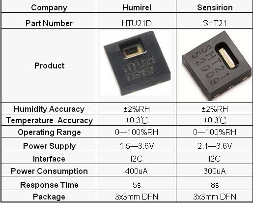
Digital Humidity Sensor Pin to Pin Replace Sensirion SHT21 - HTU21

Digital Humidity Sensor Pin to Pin Replace Sensirion SHT21 - HTU21

HTU21, the new humidity and temperature sensor of MEAS is about to set new standards in terms of size and intelligence: Embedded in a reflow solderable Dual Flat No leads (DFN) package of 3 x 3mm foot print and 1mm height it provides calibrated, linearized signals in digital, I²C format.
Digital Humidity Sensor Pin to Pin Replace Sensirion SHT21

Product Specification

Digital Humidity Sensor Pin to Pin Replace Sensirion SHT21 - HTU21


DESCRIPTION
HTU21, the new humidity and temperature sensor of MEAS is about to set new standards in terms of size and intelligence: Embedded in a reflow solderable Dual Flat No leads (DFN) package of 3 x 3mm foot print and 1mm height it provides calibrated, linearized signals in digital, I²C format.

HTU21 sensors are dedicated humidity and temperature plug and play transducers for OEM applications where reliable and accurate measurements are needed. Direct interface with a micro-controller is made possible with the module humidity and temperature digital outputs. HTU21 sensors are low power consumption designed for high volume and cost sensitive applications with tight space constraints.
Every sensor is individually calibrated and tested. Lot identification is printed on the sensor and an electronic identification code is stored on the chip – which can be read out by command.
Furthermore, the resolution of HTU21 sensor can be changed by command (8/12bit up to 12/14bit for RH/T), low battery can be detected and a checksum improves communication reliability.
With made improvements and the miniaturization of the sensor the performance-to-price ratio has beenimproved – and eventually, any device should benefit from the cutting edge energy saving operation mode.
Parameters:
1)storage temperature: -40 to 125ºC
2)supply voltage: 3.8V
3)Humidity Operating Range: 1-100%RH
4)Temperature operating range: -40 to 125ºC
5)VDD to GND:-0.3 to 3.6V
6)Digital I/O pins (DATA/SCK) to VDD:-0.3 to VDD+0.3v
7)-10 to +10 mA
Features:
(1)DFN type package
(2)Relative Humidity and Temperature Digital Output, I2C interface
(3)Fully calibrated
(4)Lead free sensor, reflow solderable
(5)Low power consumption
(6)Fast response time and very low temperature coefficient

2016年11月8日星期二

How Does an NDIR CO2 Sensor Work?

How Does an NDIR CO2 Sensor Work?
In our industry, many of us use the term "NDIR CO2 sensor", without thinking about what it stands for, or how NDIR sensors actually work.


NDIR is an industry term for "nondispersive infrared", and is the most common type of sensor used to measure CO2.

An infrared (IR) lamp directs waves of light through a tube filled with air toward an IR light detector, which measures the amount of IR light that hits it. As the light passes through the tube, any gas molecules that are the same size as the wavelength of the IR light absorb the IR light light only, while letting other wavelengths of light pass through.
Next, the remaining light hits an optical filter that absorbs every wavelength of light except the exact wavelength absorbed by CO2.

Finally, an IR detector reads the amount of light that was not absorbed by the CO2 molecules or the optical filter.

The difference between the amount of light radiated by the IR lamp and the amount of IR light received by the detector is measured. The difference is proportional to the number of CO2 molecules in the air inside the tube.

Of course, this is a very simplified explanation. If you want to learn more about NDIR, this Wikipedia article is a great place to start.

UV Sensor Sales Industry

The UV Sensor Sales Market report provides a basic overview of the UV Sensor Sales including definitions, classifications, applications and market Sales chain structure. The UV Sensor Sales Market report enlists several important factors, starting from the basics to advanced market intelligence which play a crucial part in strategizing.
UV Sensor Sales Market Opportunities:
With a purpose of enlightening new entrants about the possibilities in this market, this report investigates new project feasibility. Various details about the manufacturing process such as market drivers, impact of drivers, market challenges and impact of drivers and challenges, market trends, vendor landscape analysis and so on, is discussed in the report.
UV Sensor Sales Industry Key Players Analysis:
A complete analysis of the competitive landscape of the UV Sensor Sales market is provided in the report. This section includes company profiles of market key players. The profiles include contact information, gross, capacity, product details of each firm, price, and cost are covered.
·        ST Microelectronics
·        LAPIS Semiconductor Co., Ltd.
·        Vernier
·        Scitec Instruments Ltd.
·        Solar Light Company
The Report Provides Insights on Major UV Sensor Sales Market Points such as:
• Applications of UV Sensor Sales Market
• Manufacturing Cost Structure Analysis of UV Sensor Sales Market
• Raw Materials Sources Analysis of UV Sensor Sales Market
• Price, Cost, Gross and Gross Margin Analysis of UV Sensor Sales Market
• Supply, Consumption and Gap of UV Sensor Sales Market 2016-2021
• New Project SWOT Analysis of UV Sensor Sales Market
Analysis of Price, Cost, Gross Margin for Major Regions:
This particular section of the UV Sensor Sales market report includes analysis of gross margin, cost and price. The UV Sensor Sales Market is divided into the following segments based on geography:
• USA
• China
• Europe
• Japan
• India
• Southeast Asia
No. of Report Pages: 115
Price of Report (Single User Licence): $4000
In this UV Sensor Sales Market report analysis, traders and distributors analysis is given along with contact details. For material and equipment suppliers also, contact details are given. Production plants, their capacities, global production and revenue are studied. Also, the UV Sensor Sales Market growth in various regions and R&D status are also covered.